|
|
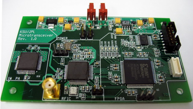
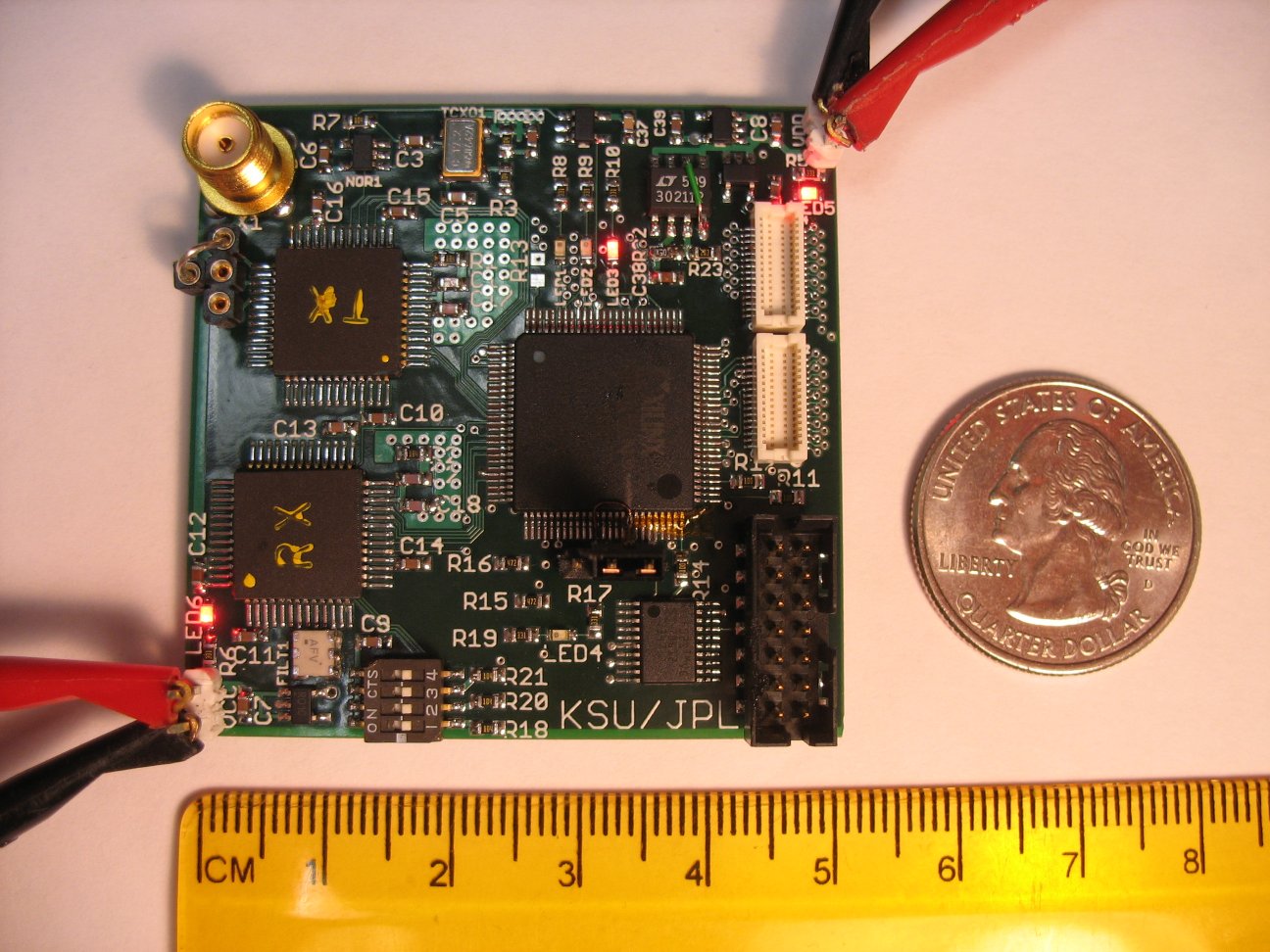
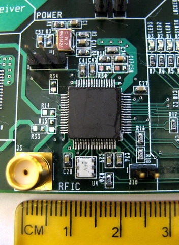
System Test and Demonstration Board
The Mars Mictrotransceiver Evaluation Board above includes the fully-integrated 100 mW RFIC transceiver (center), an optional 1-Watt RF power amplifier (left), an FPGA for digital modem functions (right), and voltage regulators (top). Total size of the evaluation board is 9cm x 5.5 cm x 1 cm, and can be reduced to less than half this dimension as required.
Information on the goals of our project and the research performed are contained on this site and in a recent paper published in Proceedings of the IEEE. Please see our publications and other links at left for more information on the many phases of the development efforts.
Mission Planners interested in applying the microtransceiver on future Mars Scout projects are encouraged to contact the developers for the latest information.
Project Background
|
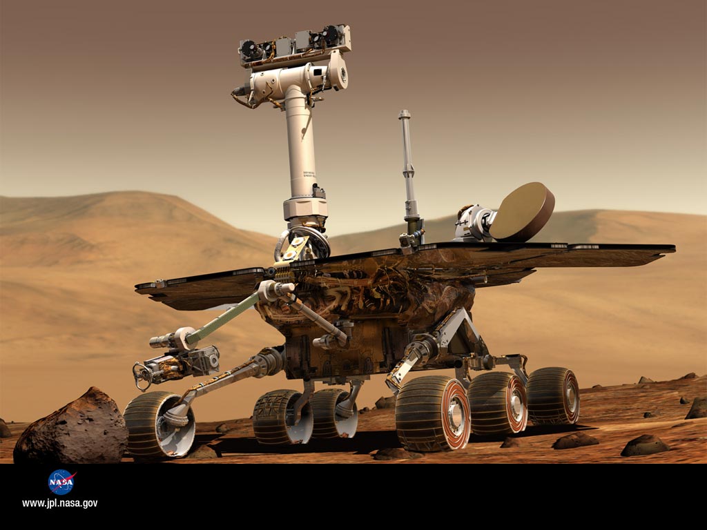
 NASA's goals for Mars exploration include "follow the water" to determine where to look for past or present life, plus a host of studies of the planet's history and current environment. These tasks were started with early missions such as Viking,
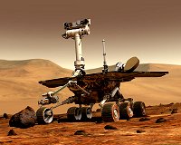
and continue today with the Spirit and Opportunity rovers as well as
through the watchful eyes of orbiters like Mars Global Surveyer, Mars Odyssey, Mars Express, and most recently the Mars Reconnaissance Orbiter (MRO). However, much more of the planet needs to be explored before complex missions like sample-return, and ultimately human presence, are undertaken.
The UHF micro-transceiver project documented in these pages provides an enabling technology for significant expansion of the planetary search. NASA's goals for Mars exploration include "follow the water" to determine where to look for past or present life, plus a host of studies of the planet's history and current environment. These tasks were started with early missions such as Viking,
and continue today with the Spirit and Opportunity rovers as well as
through the watchful eyes of orbiters like Mars Global Surveyer, Mars Odyssey, Mars Express, and most recently the Mars Reconnaissance Orbiter (MRO). However, much more of the planet needs to be explored before complex missions like sample-return, and ultimately human presence, are undertaken.
The UHF micro-transceiver project documented in these pages provides an enabling technology for significant expansion of the planetary search. |
Microtransceiver Prototyping
|
|
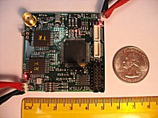 Our work is being conducted to support future Mars scout missions. The project has succeded in reducing power consumption of Mars scout radio electronics by one to two orders of magnitude. While transceivers used aboard the Mars Exploration Rovers measure as much as 2000 cm3,
weigh up to 2 kg (on earth), and consume as much as 70 Watts of power,
the micro-transceiver occupies only a few square inches of PC board space (demonstration boards shown here and above) and consumes as little as 300 mW. This opens the door for sending multiple small scouts in a single launch for more extensive exploration, and for developing aerobots, balloons, and networked lander craft. Kansas State University's Department of Electrical and Computer Engineering is partnered
with Caltech's Jet Propulsion Laboratory and with Peregrine Semiconductor in this effort. K-State's role is to deliver the radio frequency (RF) circuit portions of the Micro-transceiver, while JPL provides the
digital IC, and Peregrine Semiconductor provides the radiation-tolerant Silicon-on-Sapphire fabrication expertise. Our work is being conducted to support future Mars scout missions. The project has succeded in reducing power consumption of Mars scout radio electronics by one to two orders of magnitude. While transceivers used aboard the Mars Exploration Rovers measure as much as 2000 cm3,
weigh up to 2 kg (on earth), and consume as much as 70 Watts of power,
the micro-transceiver occupies only a few square inches of PC board space (demonstration boards shown here and above) and consumes as little as 300 mW. This opens the door for sending multiple small scouts in a single launch for more extensive exploration, and for developing aerobots, balloons, and networked lander craft. Kansas State University's Department of Electrical and Computer Engineering is partnered
with Caltech's Jet Propulsion Laboratory and with Peregrine Semiconductor in this effort. K-State's role is to deliver the radio frequency (RF) circuit portions of the Micro-transceiver, while JPL provides the
digital IC, and Peregrine Semiconductor provides the radiation-tolerant Silicon-on-Sapphire fabrication expertise.
|
Developed for the Martian Environment
|
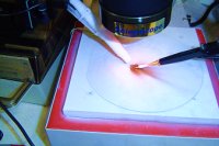 Mars is much colder than Earth due to it's added distance from the Sun. Average daily temperatures hover around -60 Celsius (-76 F), while nighttime lows
dip to as much as -120 C (-184 F). The micro-transceiver is being designed to withstand these extremes so that the traditional "warm-box" used on the rovers is not
required. This will further save on mass, volume, and power in scout-craft development. K-State has designed-in this temperature tolerance through careful studies of the operation of the electrical components at cryogenic temperatures. In addition, the designs will use a hardened version of the Peregrine SOS IC process to tolerate levels of radiation present on the Martian world. Mars is much colder than Earth due to it's added distance from the Sun. Average daily temperatures hover around -60 Celsius (-76 F), while nighttime lows
dip to as much as -120 C (-184 F). The micro-transceiver is being designed to withstand these extremes so that the traditional "warm-box" used on the rovers is not
required. This will further save on mass, volume, and power in scout-craft development. K-State has designed-in this temperature tolerance through careful studies of the operation of the electrical components at cryogenic temperatures. In addition, the designs will use a hardened version of the Peregrine SOS IC process to tolerate levels of radiation present on the Martian world. |
RFIC Design
|
 Kansas State University's role in this project is to develop and demonstrate the RF circuit portion of the micro-transceiver. The RFIC shown in green contains a fully-integrated transmitter and superhet receiver (minus an off-chip IF filter) and is capable of outputting 100 mW of RF power.
For higher-power operation, a second
IC can be attached as shown. On transmit, the RFIC modulates data onto a 400 MHz carrier for transmission to an orbiter or surface relay. Data rates from 1 kbps to as high as 256 kbps are supported (depending on link budgets) through coded BPSK, RC-BPSK, or QPSK formats. On receive, the RFIC downconverts 435 MHz command signals to a 10.7 MHz IF, filters the signal, and sends it to the companion digital IC using a 1-bit oversampled ADC. Receive data rates vary from 2 kbps to 8 kbps depending on link budgets. Kansas State University's role in this project is to develop and demonstrate the RF circuit portion of the micro-transceiver. The RFIC shown in green contains a fully-integrated transmitter and superhet receiver (minus an off-chip IF filter) and is capable of outputting 100 mW of RF power.
For higher-power operation, a second
IC can be attached as shown. On transmit, the RFIC modulates data onto a 400 MHz carrier for transmission to an orbiter or surface relay. Data rates from 1 kbps to as high as 256 kbps are supported (depending on link budgets) through coded BPSK, RC-BPSK, or QPSK formats. On receive, the RFIC downconverts 435 MHz command signals to a 10.7 MHz IF, filters the signal, and sends it to the companion digital IC using a 1-bit oversampled ADC. Receive data rates vary from 2 kbps to 8 kbps depending on link budgets. |
Digital Control and Modem IC
|
|
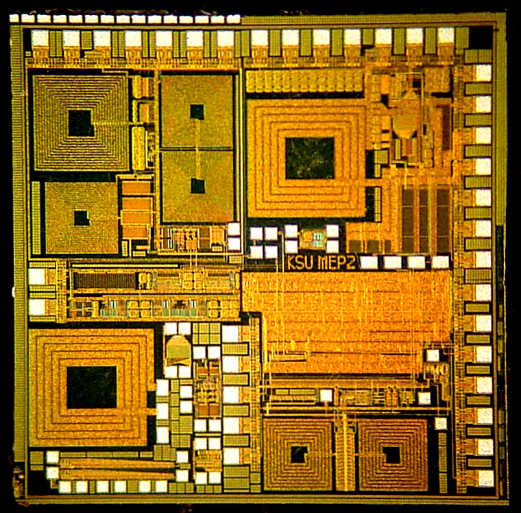
 The companion digital IC shown above is being developed at JPL. This chip will provide the interface between a scout-craft's microprocessor and the RF electronics. On transmit, it performs formatting and coding of packets compatible with the Prox-1 space protocols,
as well as the necessary housekeeping functions synthesizer programming
and power control. On receive, its duties are expanded. The RFIC supplies the IF output in 1-bit oversampled form to the digital IC which is then responsible for all carrier acquisition/sync functions as well as bit decisions and error-check decoding. The companion digital IC shown above is being developed at JPL. This chip will provide the interface between a scout-craft's microprocessor and the RF electronics. On transmit, it performs formatting and coding of packets compatible with the Prox-1 space protocols,
as well as the necessary housekeeping functions synthesizer programming
and power control. On receive, its duties are expanded. The RFIC supplies the IF output in 1-bit oversampled form to the digital IC which is then responsible for all carrier acquisition/sync functions as well as bit decisions and error-check decoding.
|
Testing
|
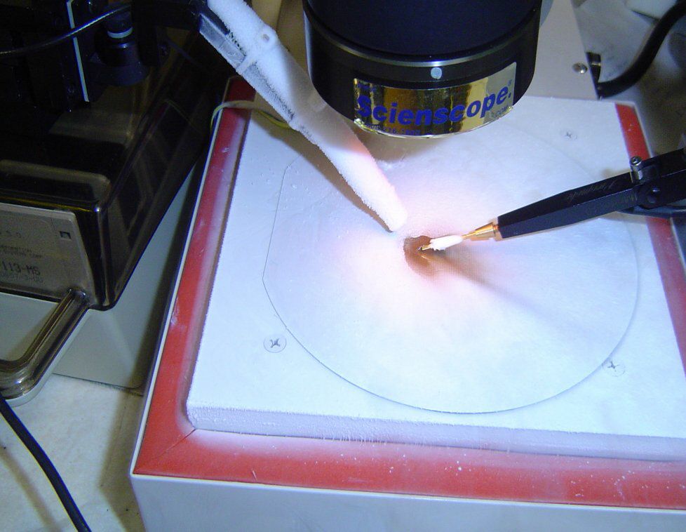
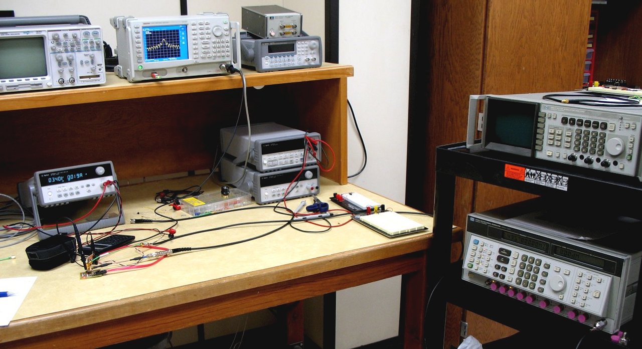
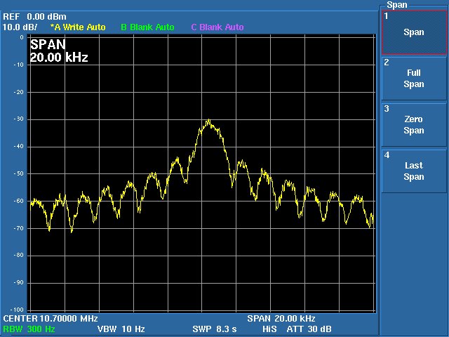
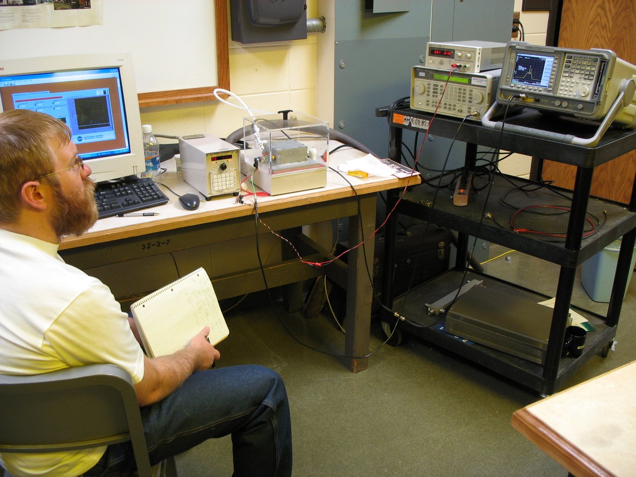
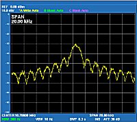 Testing is an integral part of all design activities. We test each circuit and subsystem as it is being designed, first analytically, then through simulation and layout-versus-schematic comparisons, and finally through measurements on fabricated prototype ICs. Shown
here is the final 1-bit sampled IF output
spectrum from the first prototype receiver IC - verifying end-to-end (RF to IF) functionality. Digital demodulation techniques are validated similarly, beginning with detailed analysis and Matlab simulation, and then through hardware description language coding, and finally through hardware test. As these parallel, subsystem activities are merged into larger units, testing moves to measuring performance and verifying that circuits work properly at all
temperatures. Testing is an integral part of all design activities. We test each circuit and subsystem as it is being designed, first analytically, then through simulation and layout-versus-schematic comparisons, and finally through measurements on fabricated prototype ICs. Shown
here is the final 1-bit sampled IF output
spectrum from the first prototype receiver IC - verifying end-to-end (RF to IF) functionality. Digital demodulation techniques are validated similarly, beginning with detailed analysis and Matlab simulation, and then through hardware description language coding, and finally through hardware test. As these parallel, subsystem activities are merged into larger units, testing moves to measuring performance and verifying that circuits work properly at all
temperatures. |
Project Status
|
|
As of this writing (December 2007), the project is nearing completion and a demonstration board for a full transceiver created from our custom RFIC fabs together with a commercial FPGA digital IC has been successfully tested. Temperature testing has also been completed on RFIC prototypes
with good results.
|
Additional Information
|
|
Scout mission planners are encouraged to contact the project personnel listed below for the latest information.
A secure web site is also being developed to provide mission planners and technology development engineers with detailed design and interfacing information on the micro-transceiver hardware.
Acknowledgements:
Mars media courtesy of NASA / JPL-Caltech, and Cornell University
Project Leads:
- William Kuhn (Bill Kuhn), Kansas State University
- Norman Lay, Jet Propulsion Laboratory
- Edwin Grigorian, Jet Propulsion Laboratory
- Dan Nobbe, Peregrine Semiconductor
Engineering:
- Igor Kuperman, JPL
- Yogesh Tugnawat, K-State (now at Qualcomm)
- Xin He, K-State (now at NXP)
- Jeongmin Jeon, K-State
- Kai Wong, K-State (now at General Dynamics)
- Mark Hartter, K-State (mow at Garmin International)
- Evan Cullens, K-State (now at U Colorado)e
- Jack Harder, K-State
- Keith Kovala, K-State
- Tim Sobering, K-State,
- David Huddleston, K-State


|
|


