The Semester in Pictures
The Companies:
|
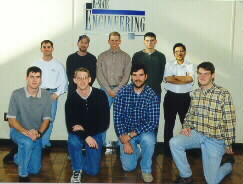
Here's the students of Company A: (Jeff Lippert not pictured)
|
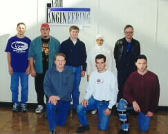
Here's the students of Company B: (Brice Pufahl not pictured)
|
Team 1: RF and Synthesizer Design
|
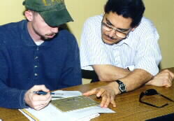
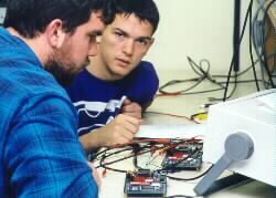
Jeremy and Nour check over the RF board prior to stuffing.
|
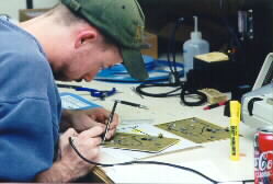
Jeremy stuffing the Company A transceiver boards.
|
|
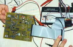
Company B's RF board and test jig
|
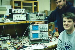
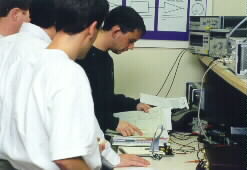
Ed and Addy testing the RF transceiver board. (1 day after this photo was taken, the entire board was operational!)
|
|
Here's the first full test of the receiver. The top trace on the scope is the 1010 data pattern modulating the signal generator. The bottom trace is the recovered data. Note the time delay caused by the bandpass filters.
|
Team 2: Digital PLD design
|
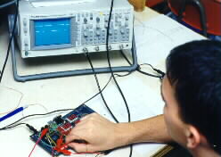
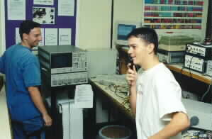
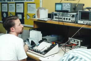
Jason performs standalone testing of the TX PLD board. The packet structure is visible on the scope!
|
Jason and Joel working on a loop-back test with the RX PLD connected to the TX PLD. Two days later, a complete test was successfully run with the ADPCM sending data to the TX PLD, the RX PLD bit and frame syncing to the data packets, and the RX PLD sending data back to the ADPCM. Beautiful fidelity.
|
|
Eric and Joel show the full loop-back test. The top scope shows the audio out of the ADPCM. The bottom scope shows the packets carrying the digitized audio.
|
David and Jason complete a successful loopback test and enjoy testing the fidelity from microphone input through the ADPCM and PLDs, and back to the speaker output.
|
Team 3: Software Engineering
|
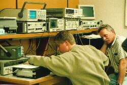
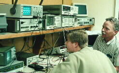
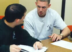
Scott and Shawn discuss software design and testing issues.
|
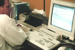
Scott Chainey debugs code using the software simulator. Two days later, the code was up and running!
|
|
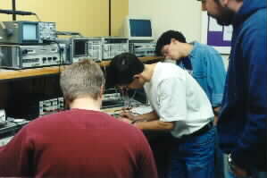
Software development team begins testing on actual hardware.
|
Shawn displays the hardware test jig used to exercise the entire program. (Approx 3000 lines of code !)
|
|
A close-up of the hardware test jig with the PLD showing the location in the software where the program is currently executing.
|
Team 4: PC Board designers and Mechanical Engineering
|
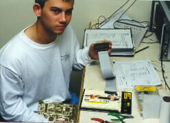
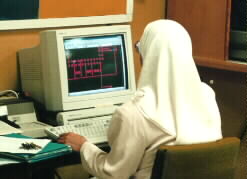
Aziza designs the digital PC board. Boards were fabricated through Alberta Printed Circuits.
|
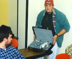
Todd shows initial construction work on the "007" briefcases in which the phone hardware will be installed.
|
Final Product Photos
These pictures show the state of development at the end of exam week. Company B has an essentially functional product with the RF board and Digital board tested together. Company A is close with a full RF board loopback test complete, and a digital board in progress.
|
Jeremy tests the synthesizer on Company A's RF board. One day later, the board passed a full loop-back test using an external mixer and power combiner to translate the transmitted RF signal back down to the received frequency and back into the antenna port.
|
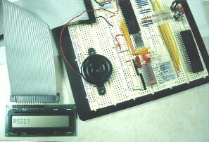
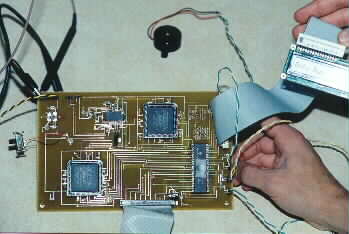
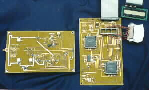
Company B's digital board, fully populated, and operational! The switch on the left is the "hook". The ICs are (clockwise from upper left), the voltage regulator, the ADPCM codec, the RX PLD, the Microcontroller, and the TX PLD.
|
|
RF, PLD, and Software teams work on final integration of the Company B digital and RF circuit boards.
|
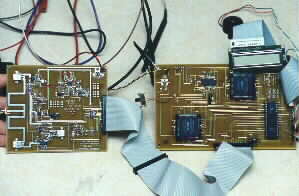
Company A's RF and digital boards. The RF board has successfully passed a loop-back test. The digital board has been powered up and should be functional soon.
|
|
Company B's RF and digital boards fully connected. After tracking down some noise problems generated by the digital board (100 mA p-p square wave currents from shorted PLD pin), the boards passed a full loopback test.
|
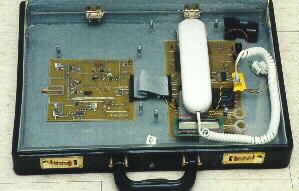
Company B's boards undergo initial installation in the "007" briefcase following successful bench testing!
|
Work on the products will continue next semester (by Jarrod Seymour and others) to get them ready for KSU's Open-House exhibit. Remaining work consists primarily of building the second board sets, more testing, and "fine tuning" of the hardware and software.
Congratulations to both companies on an excellent engineering job - designing and testing a full product in a single semester !