Powercat chevron double-chevron chat-purple home computer window with a question mark close facebook linkedin menu search twitter youtube apply-purple apply-white chat-white request-purple request-white
Jump to main contentJump to footer
Kansas State University
  • Connect
  • Canvas
  • OrgCentral
  • Navigate
  • KSIS
  • HRIS
  • Webmail
Sign in
Browse A-Z
Electrical and Computer Engineering
  • K-State home
  • Engineering
  • ECE
  • About
  • People
  • Faculty
  • William Kuhn K-State Personal Page
  • K-State RF IC Gallery

K-State RF IC Gallery

transceiver

RF probing of Copper IC

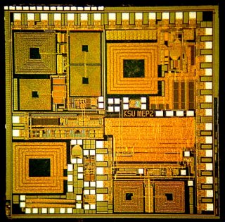
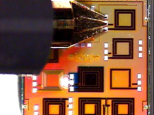
Students and faculty at K-State have created a number of analog, mixed-signal, and RF integrated circuits in class projects as well as their Masters and PhD research. Below are some examples of their layouts.

  • Mixed-signal IC with switched-cap filter, temperature sensor, and other circuits. (AMI 1.2um)
  • 200 MHz, 1-pole, on-chip bandpass filter (Orbit 2.0um)
  • 900 MHz, 2-pole, on-chip bandpass filter (HP 0.5um)
  • 200 MHz sigma-delta bandpass ADC + test spiral inductors (AMI 1.2um)
  • 400 MHz RF amplifier (AMI 1.2um)
  • 900 MHz, 1-pole, low-power on-chip BPF + test spirals (Peregrine 0.5um)
  • FM broadcast-band stereo transmitter (1.2um)
  • FM broadcast-band stereo transmitter (1.2um)
  • 1.8 GHz filter, oscillator, and test spiral inductors (0.18um, 6-metal, copper)
  • UHF transceiver in SOS
  • Layout and Photo of Inductor Library in GaAs
  • Layout and Testing of VCO and Filter in GaAs

Mike Wiegers Department of Electrical and Computer Engineering

3108 Engineering Hall

1701D Platt St., Manhattan, KS 66506

785-532-5600 | 785-532-1188 fax | ece@k-state.edu

Kansas State University
  • Contact Us
  • Emergency
  • Statements and Disclosures
  • Accessibility
  • Kansas Degree Statistics
  • KBOR Free Expression Statement
  • © Kansas State University
  • Updated
  • Updated: 7/19/24